Welding

What changes can we make to our lives to deal with the economic and energy crises ahead? Have you already started making preparations? Got tips to share?

Moderator: Peak Moderation

Little John

Post by Little John »

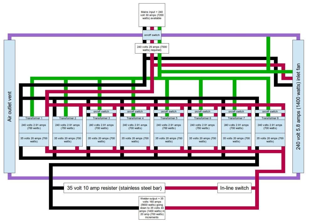
For any electrical experts on this forum....Can you see anything wrong with the following schematic for a 160-amp AC stick-welder built from eight 700-watt microwave-oven transformers? Both the primaries and secondaries are run in parallel with each other and each transformer is able to be switched individually off from the circuit in order to adjust amperage in the welder output.

The purple line is the transformer case. The red, black and green lines are positive, negative and earth wires respectively (yes, I know there is no such thing as "positive" and "negative" on AC....:wink: )

My reason for wiring the seondaries in parallel is that it allows me to have relatively high-voltage/low-amperage on each transformer secondary. This, in turn, allows me to use more readily available/scavengeable 30-amp single-core wire. Being of relatively small diameter, I should, be able to get 35 winds on the secondaries (it's approximately 1 volt per turn). I can then pump the amperage up via wiring the secondaries in parallel. The other advantage of having relatively low amps coming out of each individual secondary is that it keeps the heat down on them. It means I have more weight because of having to use more transformers to achieve the necessary welding amps. But, that's not an issue. Finally, wiring the secondaries in parallel allows me to individually switch them off and so adjust welding amperage. I should also say, as I understand it, these transformers have shunts in them to limit the through-put to 700 watts. So, there should be no risk of runaway amperage demand at the welder end.

The parallell resister on the welding output side can be switched on or off to allow for 10-amp sub-incremenets on the welding amperage. I understand, though, that it is important to make sure this is switched off immediately when there is no actual welding load as the full amperage would then pass through this resister making it get very hot in short order.

I haven't got anywhere near building this yet. Indeed, I may never build it. It's just a mental exercise really.
Image
User avatar
Catweazle
Posts: 3388
Joined: 17 Feb 2008, 12:04
Location: Petite Bourgeois, over the hills

Post by Catweazle »

Resistors are specced in Ohms, not volts or amps. The switched off transformers will always have a voltage present on the primary if another transformer is live.

To be honest Steve, if you don't have the experience of dealing with mains voltages, jointing and insulation, then you'd be better off leaving this alone.
Little John

Post by Little John »

Catweazle wrote:Resistors are specced in Ohms, not volts or amps. The switched off transformers will always have a voltage present on the primary if another transformer is live.

To be honest Steve, if you don't have the experience of dealing with mains voltages, jointing and insulation, then you'd be better off leaving this alone.
I understand that resisters are specced in ohms C. I only indicated its rating in amps, though, as an indirect index of how much amps it would draw off the main welding circuit line. As I understand it, a resister in parallel reduces current on a circuit, as opposed to a resister in series, which reduces voltage. In other words, I would just experiment with different sized resisters until I could measure a drop of 10 amps on the line, whatever ohms the resister actually came to.

Regarding the voltage that would still be present on the primaries when they have been switched off at the primary side. I am surmising that it must be coming up through the secondaries...yes? Does that matter? Don't misunderstand me, I am more than prepared to be told it does matter. But, it would help me if you could explain it to me. Or does it simply sit there with nowhere to go. In other words, does the voltage that is present on a switched-off primary affect the total secondary current or voltage coming out of the welding line and/or does it also affect the proper operation of those transformers that are still switched on? If it does, then it's kind of critical for me to know precisely how and why it has that effect. Would it resolve the problem if the transformers were switched off on the secondary side? If, on the other hand, it doesn't have an effect, then it doesn't really matter does it?

However, assuming that the voltage that is still present on the primaries of those transformers that have been switched off does have a critical effect on either the eventual output current and/or the proper operation of the remaining transformers (irrespective of which side of the transformers the switches are placed), an alternative option might be to leave all transformers switched on and simply adjust the welding amps via an externally mounted bank of varying sized resisters. Say, a bank consisting of the following resisters:

35 volt 100 amps draw (0.7 ohms)

35 volt 50 amps draw (0.7 ohms)

35 volt 20 amps draw (1.75 ohms)

35 volt 20 amps draw (1.75 ohms)

35 volt 10 amps draw (3.5 ohms)

It might even be possible to scavenge some appropriately sized second- hand electric-fire bar-elements that could serve the purpose.

These could be mounted externally on a thermal and electrical isolation board and be housed in a cage. It would be less desirable option than removing transformers from the array to adjust amperage because it is less energy efficient (with resisters, the draw of the welder would be at the maximum all the time). But it would work I think.

Regarding wiring connectors (particularly on the secondary side of the transformers where there is going to be a large amount of amps), I would make these myself out of suitably sized tapped brass square bar using brass studs. I would then insulate them with heat-shrink plastic insulation tubing. I've already used these type of connectors as in-line connectors when I have extended my welding lines with old jump-starter leads and they have never run hot.
User avatar
Catweazle
Posts: 3388
Joined: 17 Feb 2008, 12:04
Location: Petite Bourgeois, over the hills

Post by Catweazle »

stevecook172001 wrote:I understand that resisters are specced in ohms C. I only indicated its rating in amps, though, as an indirect index of how much amps it would draw off the main welding circuit line. As I understand it, a resister in parallel reduces current on a circuit, as opposed to a resister in series, which reduces voltage. In other words, I would just experiment with different sized resisters until I could measure a drop of 10 amps on the line, whatever ohms the resister actually came to.

I think you're getting the function of a resistor confused. A resistor will drop a voltage dependant on both the value of the resistance and the current flowing through it. Think of it as a piece of small-bore pipe in a plumbing circuit, the more pressure (voltage ) the more water ( current ) will flow through it. However if you tried to draw too much water through it the pressure would drop very low, on the other hand if the "out" side of the small-bore pipe was sealed then the pressure ( voltage ) on both sides would equalise. This is a crude analogy, but useful. Research Ohms law thoroughly.

Regarding the voltage that would still be present on the primaries when they have been switched off at the primary side. I am surmising that it must be coming up through the secondaries...yes? Does that matter? Don't misunderstand me, I am more than prepared to be told it does matter. But, it would help me if you could explain it to me. Or does it simply sit there with nowhere to go. In other words, does the voltage that is present on a switched-off primary affect the total secondary current or voltage coming out of the welding line and/or does it also affect the proper operation of those transformers that are still switched on? If it does, then it's kind of critical for me to know precisely how and why it has that effect. Would it resolve the problem if the transformers were switched off on the secondary side? If, on the other hand, it doesn't have an effect, then it doesn't really matter does it?

It won't affect the operation, but you need to be aware of it when testing the unit, double pole switching would be a good idea.

However, assuming that the voltage that is still present on the primaries of those transformers that have been switched off does have a critical effect on either the eventual output current and/or the proper operation of the remaining transformers (irrespective of which side of the transformers the switches are placed), an alternative option might be to leave all transformers switched on and simply adjust the welding amps via an externally mounted bank of varying sized resisters. Say, a bank consisting of the following resisters:

35 volt 100 amps draw (0.7 ohms)

35 volt 50 amps draw (0.7 ohms)

35 volt 20 amps draw (1.75 ohms)

35 volt 20 amps draw (1.75 ohms)

35 volt 10 amps draw (3.5 ohms)

It might even be possible to scavenge some appropriately sized second- hand electric-fire bar-elements that could serve the purpose.

These could be mounted externally on a thermal and electrical isolation board and be housed in a cage. It would be less desirable option than removing transformers from the array to adjust amperage because it is less energy efficient (with resisters, the draw of the welder would be at the maximum all the time). But it would work I think.

Some old welding sets used a long spring with a clamp that could be moved on it to adjust the resistance, and hence the welding current.

Regarding wiring connectors (particularly on the secondary side of the transformers where there is going to be a large amount of amps), I would make these myself out of suitably sized tapped brass square bar using brass studs. I would then insulate them with heat-shrink plastic insulation tubing. I've already used these type of connectors as in-line connectors when I have extended my welding lines with old jump-starter leads and they have never run hot.
You seem to have the high-current joints covered, Ohms law helps here too - the higher the resistance of the joint the higher the power dissipated by it. IsquaredR.

Alternatively, couldn't you weigh the microwave transformers in for scrap and buy another welder with the money ?
Little John

Post by Little John »

Cheers Cat for the extensive reply to my questions. Very helpful.

That movable clamp resister you just mentioned sound pretty much like the power resistors I have seen advertised ont he net.

You're right, I am confused about resistors as I had understood that it dropped voltage in the circuit after the resister if it was connected in series on that circuit and it dropped current in the circuit after the resister in it was connected in parallel on that circuit. The way I'd been conceptualising it was that the resister needs to have some resistance but not total resistance. Thus, the electricity can get through it, but in struggling to do so, some of it is converted to heat. It is this conversion to heat in the resister that causes the rest of the parallel circuit following the resister to have lost some amps.

Are you saying that the rest of the welding circuit (following the parallel resister) will not have dropped amps if I connect a parallel resister?

Or, perhaps another way of asking the question: is the effect on the circuit’s voltage and/or amps the same irrespective of whether the resister is connected in series or parallel?

Anyhow, you're right about the scrap value... :lol:

It would be barely worth building one of these things unless you could scrounge absolutely every singe component from scrap.
User avatar
Catweazle
Posts: 3388
Joined: 17 Feb 2008, 12:04
Location: Petite Bourgeois, over the hills

Post by Catweazle »

stevecook172001 wrote:Cheers Cat for the extensive reply to my questions. Very helpful.

That movable clamp resister you just mentioned sound pretty much like the power resistors I have seen advertised ont he net.

You're right, I am confused about resistors as I had understood that it dropped voltage in the circuit after the resister if it was connected in series on that circuit and it dropped current in the circuit after the resister in it was connected in parallel on that circuit.

Are you saying that the rest of the welding curcuit (following the parallel resister) will not have dropped amps if I connect a prallel resister?

The water analogy works here too. Imagine one welder output is your hosepipe and the other is the grass. A parallel resistor is the equivalent of a hole in your pipe, letting some water go straight to the grass before it gets to the end of the hosepipe. So, yes, there will be less current available at the work end of the hosepipe but your tap ( transformer ) will still be working just as hard. Imagine that you have a spray head on the hosepipe, when the head is off the pressure in the pipe will cause more water to spurt from the hole in the pipe, but when the spray head is wide open less will leak from the whole, the water preferring the easy route out of the spray head. The spray head could illustrate the welding rod either in use ( open valve ) or not.

Anyhow, you're right about the scrap value... :lol:

It would be barelty worth building one of these things unless you could scrounge absolutely every singe component from scrap.
JavaScriptDonkey
Posts: 1683
Joined: 02 Jun 2011, 00:12
Location: SE England

Post by JavaScriptDonkey »

You may want to factor in where the back EMF will try to run to when you switch it off. I should imagine the collapsing field of 7 microwave transformers will induct a hefty current somewhere.
User avatar
Catweazle
Posts: 3388
Joined: 17 Feb 2008, 12:04
Location: Petite Bourgeois, over the hills

Post by Catweazle »

JavaScriptDonkey wrote:You may want to factor in where the back EMF will try to run to when you switch it off. I should imagine the collapsing field of 7 microwave transformers will induct a hefty current somewhere.
I don't think that would be a problem, as if there is no load on the secondarys there will be little current flowing in the primaries. Switching it of whilst actually welding would be a different matter, it should be protected by a type of fuse of sufficient breaking capacity.
Little John

Post by Little John »

mmmmmm......been thinking again...always a bad move.... :lol:

What about rewinding the secondaries on a couple of old step-down power-tool site-transformers. They typically come in at 240 volts 3500 watts, which is about 14.5 amps input I think. The secondaries (110 volts) could be stripped out and rewound to 22 volts. at which point they would be be pushing out 22 volt - 159 amps. two of these secondary rewound transformers could be connected in parallel on the primary side and in series on the secondary side. This would give a combined secondary output of 44 volts - 159 amps; pretty much perfect for welding. The input would just about run on a 30 amp 240 volt supply (14.5 * 2 = 29)

I've just nipped in my shed and taken a look inside my pretty standard 3.5 KV step down site transformer (240 to 110 volts) and it basically looks like a very large microwave transformer (E shaped core, meaning primary and secondary are not wound on top of one another). So, stripping out and rewinding the secondaries should be fairly easy on these. It even has a thermal cut-out built into it and so a welder rigged up from a couple of these could re-employ the thermal cut-outs off them for extra safety.

The only thing I can't tell without having a closer look is if they have shunts in to limit them like they have on microwave transformers. I would have thought they would have though.

One thing that concerns me, though, is that with 159 amps coming out of each of the transformer secondaries, that would require some extremely hefty single core wire in the secondaries to handle and it would probably be prohibitively expensive to get hold of. That being the case, as described in the microwave transformer array I mentioned up-thread, the secondaries could be wired up in parallel to double the amps whilst holding the voltage constant. Thus, they would need to be wound a higher number of turns to bring the amps down on each transformer (in order that the welder didn't end up with a stupidly high number of combined amps on the secondary side). Say, 44 volts on the secondary side of each transformer giving about 80 amps (indeed, a single transformer, wired in this way, would basically be a 44 volt-80 amp welder) Thus, paralleled up on the secondary side would give roughly 160 amps in total.

80 amps, though, would still need a reasonably hefty cable in the secondaries. In lieu of this, I have a question. Possibly an extremely stupid question, but I am going to ask it nonetheless;

Would simultaneously winding three, identical, single-core, 30-amp wires exactly the same number of turns on the secondary side and then connecting their respective ends as they came out of the secondary, thus presumably combining their output, produce the same voltage/amperage output (combined) as using one single core 90 amp wire? My initial sense is that it would be the same since the wires would be in parallel and so the voltage would be held constant whilst the total amperage would be the sum of the amperages in each of the wires. Given that the number of turns of the respective wires fixes the voltage on each of them, the available power in amps is a finite quantity (based on what the primary side is pushing out) and so must be distributed equally between the three wires (assuming they are identical in diameter and resistance). Let's say the number of turns of each of the secondary wires was such that this produced 44 volts and that had the secondary had been wound with a single wire this many times the amperage output from the secondary would have been 80 amps, then each of the three simultaneously wound wires would have to share that 80 amps between them and so each wire would only pick up 80/3 amps (26.6 amps). Thus, when they were combined as they came out of the secondary side, the amps would then sum to 80.
User avatar
adam2
Site Admin
Posts: 10926
Joined: 02 Jul 2007, 17:49
Location: North Somerset, twinned with Atlantis

Post by adam2 »

I would advise against the use of a number of modified microwave transformers connected as described.
It could be made to work, but there is so much to go wrong and so much potential for dangerous accident that the purchase of a basic ready made welder has a lot to commned it.

If transformers are to be run in parralel then they must have the same polarity, which is determined by testing, and also the same turns ratio.
Unless the transformers are all identical, which is unlikely in the case of reclaimed units, then they wont have the same turns ratio.
"Installers and owners of emergency diesels must assume that they will have to run for a week or more"
Little John

Post by Little John »

adam2 wrote:I would advise against the use of a number of modified microwave transformers connected as described.
It could be made to work, but there is so much to go wrong and so much potential for dangerous accident that the purchase of a basic ready made welder has a lot to commned it.

If transformers are to be run in parralel then they must have the same polarity, which is determined by testing, and also the same turns ratio.
Unless the transformers are all identical, which is unlikely in the case of reclaimed units, then they wont have the same turns ratio.
I would have thought that as long as they are the same wattage output, the turns ratio should be fairly easy to establish. Simply temporarily wind a few turns of wire on the secondary and then measure the voltage. Then divide the number of turns by the volts. This will give you the number of turns per volt on any given unit.
User avatar
adam2
Site Admin
Posts: 10926
Joined: 02 Jul 2007, 17:49
Location: North Somerset, twinned with Atlantis

Post by adam2 »

Yes the turns ratio and/or volts per turn could be measured as described, but what then ? It can not easily be altered.
The mains winding is best not altered in the inrterests of saftey, and the new low voltage winding will probably have so few turns that sufficiently fine adjustment is not possible.
If the new secondary winding has only 10 turns, then clearly the smallest alteration that can be made is to add or subract one turn, a difference of 10% Much closer adjustment than that is needed for transformers to work in paralell.
"Installers and owners of emergency diesels must assume that they will have to run for a week or more"
Little John

Post by Little John »

adam2 wrote:Yes the turns ratio and/or volts per turn could be measured as described, but what then ? It can not easily be altered.
The mains winding is best not altered in the inrterests of saftey, and the new low voltage winding will probably have so few turns that sufficiently fine adjustment is not possible.
If the new secondary winding has only 10 turns, then clearly the smallest alteration that can be made is to add or subtract one turn, a difference of 10% Much closer adjustment than that is needed for transformers to work in parallel.
The mains primary winding won't be touched. Typically, these small transformers work out at about 1 turn per volt on the secondary side. For arc welders, they would need about 40 volts on the secondary side. So, even if a transformer secondary worked out at, say, something awkward like 1 and 1/5 turns per volt, this is easily calculated as 6 turns to 5 volts. Thus, the voltage could be set on the secondary side as a multiple of 5 so that it came to a full set of turns (in this case, exactly 40 volts). The fact that, with some turn ratios, this might cause the voltage to have to come out a few volts either side of 40 is not critically relevant since welders typically employ an output voltage anywhere from about 30 to 50 volts.

In any event, even if the secondary side came out at, say, 40 and 5/7 volts, this doesn't really matter anyway does it, as long as both secondaries are identical in their voltage. A secondary side voltage doesn't care if it is an integer or mixed number does it?
Last edited by Little John on 19 Oct 2012, 13:33, edited 3 times in total.
User avatar
Catweazle
Posts: 3388
Joined: 17 Feb 2008, 12:04
Location: Petite Bourgeois, over the hills

Post by Catweazle »

stevecook172001 wrote:Would simultaneously winding three, identical, single-core, 30-amp wires exactly the same number of turns on the secondary side and then connecting their respective ends as they came out of the secondary, thus presumably combining their output, produce the same voltage/amperage output (combined) as using one single core 90 amp wire? .
That would be fine, there is no need to use single cored wire in the transformer, you could use heavy stranded wire if you like.
Little John

Post by Little John »

Catweazle wrote:
stevecook172001 wrote:Would simultaneously winding three, identical, single-core, 30-amp wires exactly the same number of turns on the secondary side and then connecting their respective ends as they came out of the secondary, thus presumably combining their output, produce the same voltage/amperage output (combined) as using one single core 90 amp wire? .
That would be fine, there is no need to use single cored wire in the transformer, you could use heavy stranded wire if you like.
Ah yes, I know about using stranded wire as opposed to using solid core Cat. What I am referring to is taking 3 independent, insulated, 30-amp wires of identical resistance and winding them simultaneously and then joining their respective ends (positive to positive and negative to negative) when they came out of the secondary. Assuming that they were wound to produce 40 volts and (given the total wattage) the total amperage available was, say, 90 then I am assuming that each of the 3 individual wires would pick up 30 amps each on the winding, which would then be recombined when they came out of the secondary to produce a combined amperage reading of 90 amps.
Post Reply